
 Time-Saving and Extremely precise with CT Analyzer
Efficient testing of current transformers with the CT Analyzer
 Current transformers are used for measurement and protection purposes. They establish galvanic isolation between the high voltage of the power system and the low-voltage secondary technology while converting relatively high currents into low, safe and reliably measurable variables. These transformers often contain an iron core. If the test engineer is familiar with the properties and behavior of the core, it will help him assess the performance of the transformer when in use. The CT Analyzer from OMICRON offers valuable assistance,
as it enables simple analysis of the iron core and time-saving testing of the transformer’s
behavior under various operating conditions.
When currents are being transformed, losses occur in a current transformer which are primarily influenced by its core. If this behavior is considered based on an equivalent circuit diagram, losses of this nature can be depicted using a non-linear component (ZE) connected in parallel (Figure 1). The magnetizing current flows via this component. If this is plotted across the operating range, one gets the magnetization curve.
The flux density (B) and the magnetic force (H), generated from the primary current, are represented in a diagram (B-H characteristic curve). The shaded area represents the hysteresis losses, which correspond to the energy converted to heat in the core (Figure 2).
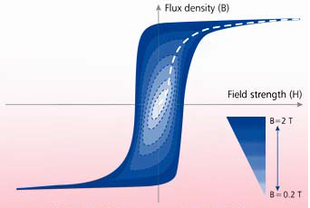
The magnetization curve intersects at the turning point of the hysteresis loop and is often specified by the manufacturer of the current transformer.
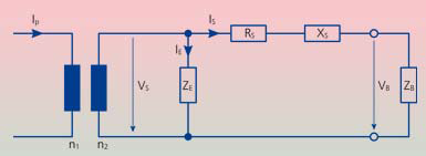
Figure 1:Equivalent circuit diagram of a current transformer.
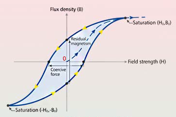
Figure 2: Hysteresis loop. The enclosed area represents the hysteresis losses.
 Innovative testing: CT Analyzer
High test voltages can be avoided by using the CT Analyzer from OMICRON. The maximum voltage applied by this device is 120 V. If the transformer is not magnetically saturated after applying this voltage, the frequency gets reduced in order to increase the flux density while maintaining the voltage. Once the tests are completed, the core is automatically demagnetized to remove any remanence. Using this innovative approach, a level of saturation can be achieved that corresponds to a theoretically applied excitation voltage of up to 30 000 V without the actual voltage
ever exceeding 120 V.
Advantages for the test engineer
The CT Analyzer offers many advantages to its users. Of particular importance is the inherent safety of the process which results from a maximum testing voltage of 120 V. It is easy to transport, as it is very compact and weighs just 8 kg (17.6 lbs). As the device only needs to apply a relatively low output, it has been possible to drastically reduce its weight and dimensions when compared with conventional testing equipment. Using the CT Analyzer also offers
increased protection for the current transformer itself, as accidental errors on the part of the test engineer, such as increasing the voltage too quickly, are prevented, eliminating the risk of damage to the core or shorted windings due to flashovers.
Innovative testing: A maximum applied voltage of 120 V. The frequency will be reduced if the transformer is still not magnetically saturated.
 Precise modeling
The CT Analyzer also measures other parameters, such as eddy current losses, core ratio and winding resistance and hence it is capable of producing a precise model of the current transformer. The transformer’s parameters, specified in line with international standards such as IEC 60044-1, IEC 60044-6 or IEEE C57.13, can be both calculated and evaluated. The CT Analyzer is provided with regular software updates which allow it to maintain compatibility with industry changes.
 Time-consuming and costly conventional testing
For protective applications, the saturation point is a key factor when dimensioning current transformers. It must be high enough to ensure that the current transformer is capable of transforming the currents flowing on the primary side to the secondary with sufficient precision in the event of a system fault which is the only way to secure a correct protective relay response. Although nominal specifications are in place for this, in practice it is generally not possible to assess whether a current transformer is capable of complying with the class stated on its name plate (e.g. 5P20).
If the current transformer is being used for measurement purposes, the accuracy of the specified primary nominal current is the most important parameter. The current transformer must be capable of maintaining its minimum accuracy in terms of measured current error and phase displacement up to the rated secondary load stated which, if not the case, will lead to billing errors. Conventional testing of current transformers is a very time-consuming process, usually requiring the transformer to be transported to a laboratory or workshop, as the testing procedure requires extensive test equipment, including an external load.
CT Analyzer: Simple, time-saving and extremely accurate measurements
The CT Analyzer allows reliable and precise evaluation of current transformers. Testing is performed on-site and without the need for external loads. The measured current error and phase displacement are determined for all requisite test points, and the typical time necessary for testing is less than one minute.
Independent metrological laboratories have confirmed that the CT Analyzer is capable of precise current transformer testing up to the accuracy class of 0.1— corresponding to the highest specification defined in the IEC and IEEE standards.
CT Analyzer
> Highest measurement accuracy: Its extremely high accuracy (typically 0.02 % / 1‘) allows the testing of current
transformers up to the accuracy class 0.1
> Very compact and lightweight (< 8 kg / 17.4 lbs): Easy to transport and ideal for on-site testing
> Automatic evaluation in line with IEC and IEEE standards
> Shorter commissioning times: The automatic test generally takes less than 1 minute
> Excellent workplace safety: Testing with maximum voltages of just 120 V
> Integration into testing routines using Remote Interface Control
> Automatic demagnetization of the transformer after every test
> Covers transformers with transient behavior
(e.g. TPX, TPY, TPZ) and with knee point voltages up to 30 kV
Tham khảo:
http://www.omicron.at/ctanalyzer